Background to Development
Background to Development
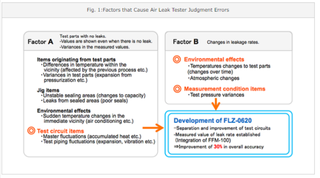
Changes in the outside environment (time, temperature, atmospheric pressure, testing pressure, and rate variance), all have an effect on air leak testing.
Testing locations can also be subject to environmental changes that effect test results such as the season and time of testing, altitude and regional variances at different testing sites, as well as atmospheric pressure and temperatures etc. An example of this could be the difference in the testing environment between morning and night. In terms of leak rates that we would expect from the same test parts with the same sized leak point, the temperature and pressure difference of these two time frames will cause an effect on the test results. Additionally, pressure variance can also be a factor in some test parts that do not have any leaks where the results achieved can show what could be seen as a leak. This type of phenomenon has been a problem for many users and technicians to date.
At Fukuda, we have placed our emphasis on the factors that cause errors on judgment as shown in the orange section in Fig. 1, and have developed a new auto-calibration air-leak tester (FLZ-0620).
Leak testing using a leak hole as a reference
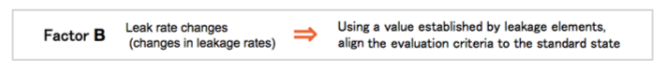
What cause changes in the leak rate?
Leak ranges for air leaks in air leak testers are based mainly on viscous flows. As shown in the Theoretic Model of Leakage in the left section of Fig. 2, when fluid passes through extremely small or narrow areas, the formula shown in Fig. 2 is applicable if the leak is in the range of a viscous flow. Here, as there is a viscosity coefficient for change due to a change in temperature, this will be the variation factor for the flow rate. Leak rates can also change due to contraction and expansion.
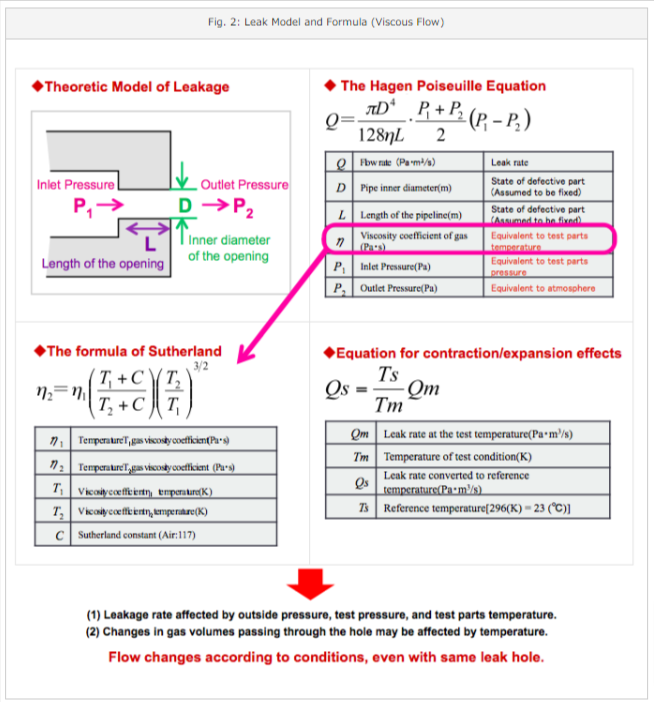
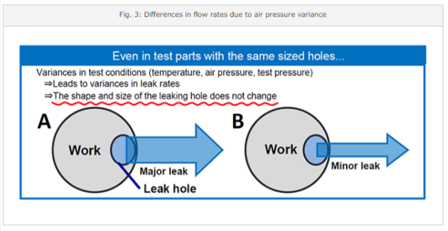
In other words, even if the leakage hole in the test part is the same, due to fluctuations in the test conditions (mainly air pressure and temperature), the amount of leakage occurrence can differ. For example, as shown in Fig. 3, even in test parts that have the same sized hole, there will be a different amount of leakage occurring in A and B depending on the difference in the applied air pressure. Where the size of the leak hole itself is the same, the leak rate will change depending on the variation of the testing conditions (temperature, air pressure, test pressure).
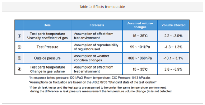
As summarized in Table 1, we can expect between a 5-20% difference to be seen as an effect on leak rates due to changes in the exterior environment.
If leak testing is carried out purely to find out leak amounts without standardizing the testing conditions, the test standard will also change due to changes in the testing conditions (air pressure and temperature etc.). When addressing this issue, measuring each parameter of the test conditions (test pressure, atmospheric pressure, temperature etc.) in order to prepare the testing environment is not realistic as it takes a great deal of cost and time.
Therefore rather than preparing an environment, we have developed an auto-calibration function that corrects measured leakage rates using a leakage element (FFM-100) with an established value measured under a set of preset conditions (standard state). As shown in Fig. 4, using auto-calibration, we are able to evaluate the leak rate under the same conditions even if the testing conditions change.
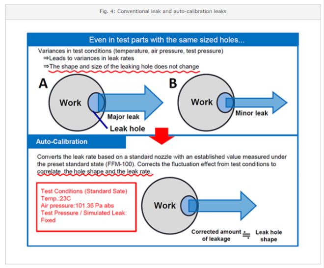
Auto calibration is a correcting function that uses actual measured values of a leakage element (variant pressure) expected to behave the same way as holes in test parts (defects). Leakage elements are elements with an established value of leakage rate measured in a standard state of a temperature of 23℃, and an air pressure level of 101.3kPa.
Rather than using the former judgment method of measuring the "actual leakage flow volume," leak rates are determined by converting the "Leak rate flow at a standard state."
Up to now, although testing was carried out in conjunction with other leakage elements, the system was treated as a "fixed constant" that would not change from the first time the test was performed, and variations in leakage rate due to the surrounding environment was considered measurement errors. This method was replaced with a new one in which values of environmental variations with a leakage element are re-measured. This system now makes it possible to adapt with environmental changes better than that of conventional models.
Auto-Calibration Function
The FLZ-0620 has a built-in FFM-100 as a leakage element, and performs conversions of leak rates automatically. The leak element ties measured pressure variance with the leakage rate according to environmental changes, allowing for corrections as needed to the standard state, bringing a leak rate evaluation under the same conditions.
Operation Principles
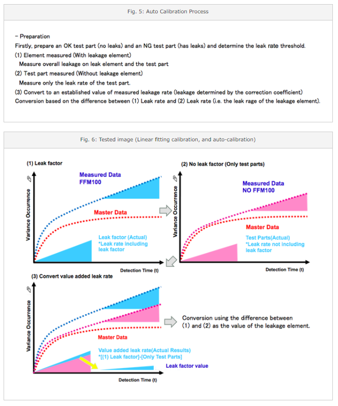
Basically the system is similar to conventional linear fitting corrections. However, the significant difference over former methods is the fact that an auto-calibrating function is included in the testing process. As shown in Fig. 5 and 6 a more precise level of testing is possible through linear fitting corrections while auto-calibration is carried out.
FLZ-0620 Calibration Example
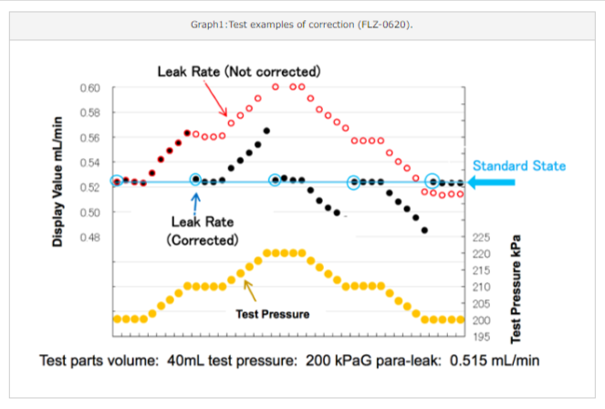
Graph 1 shows the results of a calibration using the FLZ-0620 for an intentionally made change in test pressure of 200kPa (10%). As shown by the items in red where calibration is not carried out, the leak rate also changes according to the changes in test pressure. On the other hand, as shown by the items in black where calibration is carried out, the testing value is automatically corrected to the leak rate using the standard state. In this way, there is no effect on the measuring value even if the test pressure changes (See Fig. 4)
Improved testing circuit (1) Merits of separate structure
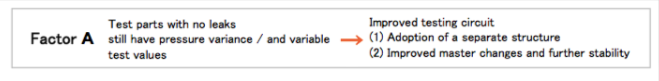
Various methods have improved on conventional models for when pressure variance is seen on test parts that do not have leaks or when there is a difference in tested values. The FLZ-0620 has achieved higher stability thanks to the unit being fitted with a further improved testing circuit and a separate structure.
(1) Merits of having a separate structure
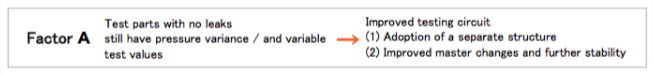
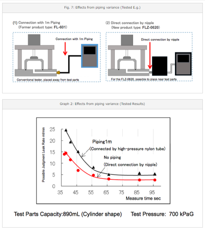
When leak testing, variances can be seen in tested values due to factors that cause unstable piping (expansion) or outside atmospheric factors (temperatures changes etc). In order to improve these areas, it is ideal to position the measuring potion of the unit as close to the test part as possible. Fig. 7 shows an example of actual effects on measurements when measured from piping of different lengths. (1) shows the piping length of the test part and the tester at 1m, and (2) showsa direct connection by nipple between the test part and the tester. Looking at the actual results, Graph 2 shows that the test value of (2) is more stable. The shorter piping to the test part brings less variance in the test values.
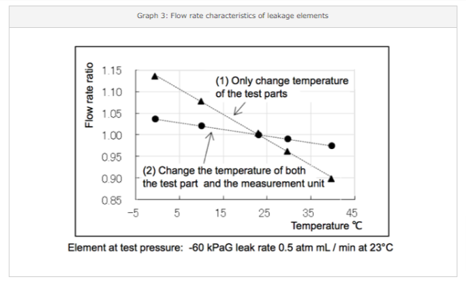
The separate structure allows the placing of test parts and the testing unit under the same temperature environment, to make it possible to minimize flow rate changes due to temperature variance. Graph 3 shows the tested results of leak rate changes when the temperature has changed. The flow rate variance level is lower (2) when the temperatures of the test part and the measuring unit are the same as compared to (1) when there is a difference in temperature of the test parts and the measuring unit.
Improved testing circuit (2) Improved and more stable master variance
Improved Master Changes (Higher stability of the master)
Improvements to the masters variances and more stable testing act as countermeasures for when values are apparent even though there are no leaks in the test parts.
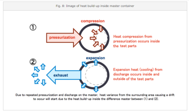
As shown in Fig. 8, there is a slight drift of testing pressure variance where fixed masters were incorporated in conventional type air leak testers due to the effect of heat accumulation from repeated pressurization and discharging.
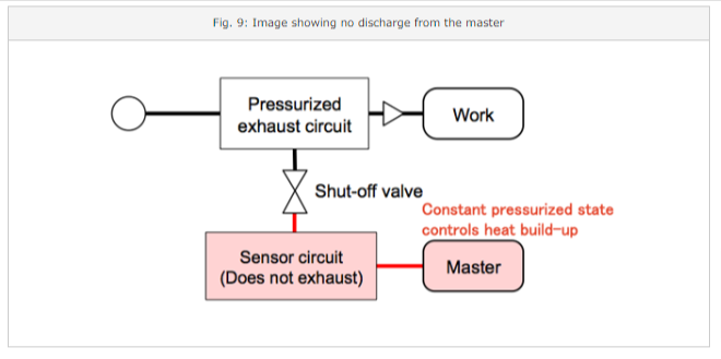
In order to remove the influence of heat compression on the master, by not discharging from the master, it is now possible to bring the drift due to heat storage down to zero as shown in Fig. 9.
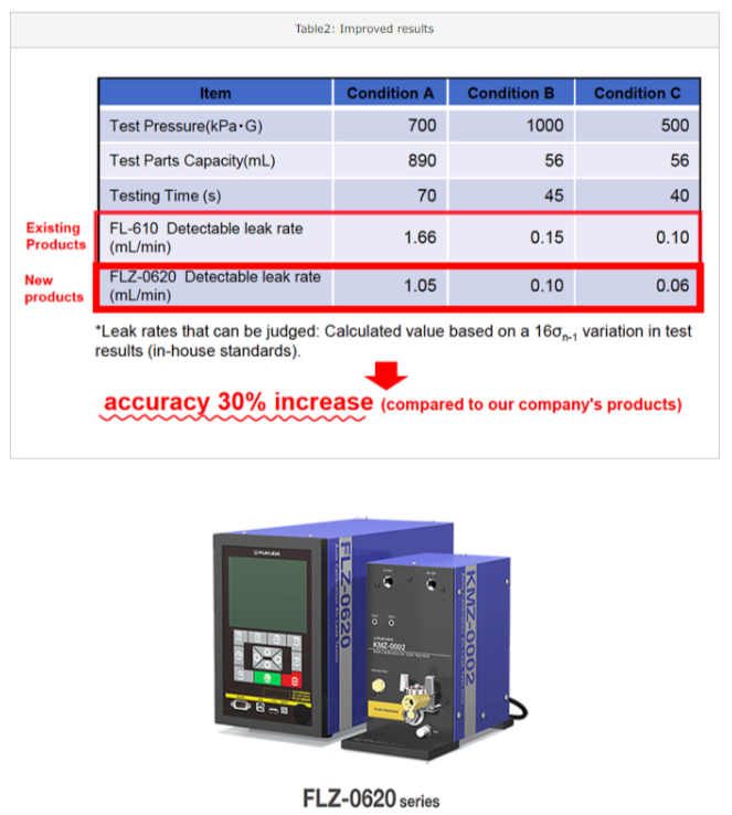
In this circuit, in addition to the above improvement, we can expect (1) prevention of foreign matter from entering the sensor, (2) avoidance of the tester failure due to dew condensation at the time of pressurization or discharge, (3) improved durability due to less stress on the pressure variance sensor. From a comparison of the Detectable leak rate on conventional products and the FLZ-0620, as shown in Table 2, the stability of the measurement has improved by 30%.