Inspection of Hermetically sealed electronic components
Inspection of Hermetically sealed electronic components
Hermetically sealed electronic components such as MEMS, crystal oscillators and semiconductor devices are used in a wide range of applications.
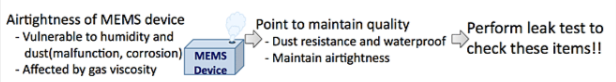
Humidity and viscosity of filler gas significantly affect the performance of MEMS devices and hermetically sealed electronic components in which malfunction due to corrosion of internal circuit by humidity and change of gas viscosity affects performance and safety. Therefore, MEMS devices are in a vacuum state or enclosed and sealed by inert gas to maintain stable performance for a long term and to prevent malfunction. To ensure the reliability of the enclosure and sealing, high enclosing technology and highly accurate leak test to judge the existence of leak is indispensable. Normally, combination of two types of measurement, namely, gross leak measurement and fine leak measurement are necessary for MEMS inspection since single leak test for airtightness inspection of enclosed MEMS and other devices cannot cover a wide range of leak rate. FUKUDA has automated complicated airtight test for MEMS and other devices and has been providing products to manufacturers in Japan and other countries that allow easier and prompt measurement compared to immersion leak test.
Leak testers for Hermetically sealed electronic components

Test method by immersion and test method by FUKUDA
The test method by immersion (Fluorocarbon + helium) and test method of FUKUDA products (air + helium) are described in the diagram below.
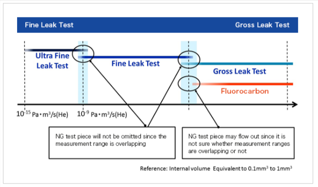
The test method by immersion judges leak by immersing the test piece in fluorocarbon and through generated bubbles. Since it is difficult to numerically express the leak rate from bubbles, the overlapping measurement range of helium leak test and fluorocarbon cannot be checked and may have a range where it is not covered by either test. Therefore, it may create a range that cannot be measured and may not be able to identify defective products. On the other hand, FUKUDA products will not omit defective products since they are able to overlap measurement ranges of helium leak test and air leak test to prevent uncovered measurement range.
Leak test by immersion
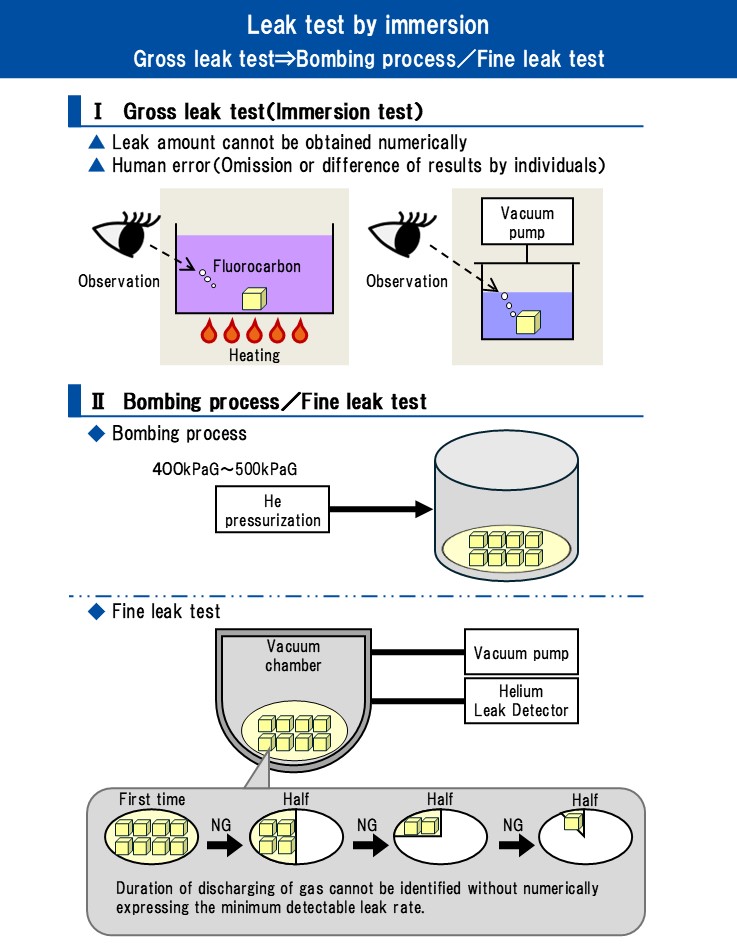
Gross leak measurement by Immersion test has a risk of human error and leak rate cannot be expressed numerically. Precise leak rate cannot be expressed numerically such as 5×10⁻⁵Pa・m³/s and 3×10⁻⁶Pa・m³/s with Immersion test. When leak rate value is not available, the limit of leak rate for removing NG test piece is unclear with gross leak measurement in which helium gas dwell time cannot be decided. Helium gas dwell time is a standard to identify how much time it takes for the gas charged in the test piece to be discharged completely when the helium gas charged inside the product is at the minimum gross detectable leak rate (the smallest leak rate that can be judged by the leak tester). There is a possibility to omit defective parts when the minimum detectable leak rate of gross leak cannot be measured by the method described in the figure above. Helium gas may be discharged and test piece may not be detected when the internal volume is at a very low level such as 0.1mm³ with the process to measure test piece in several stages. Inspection by longer dwell time is possible when highly sensitive leak rate can be obtained by gross leak measurement in which airtightness inspection can be performed stably without omitting defective products.
Leak test by FUKUDA products
Gross leak measurement has a role to identify NG test piece with large leak and ensure dwell time necessary for fine leak measurement. FUKUDA products allow controlling of dwell time by numerically expressing the leak rate during the gross leak measurement since FUKUDA products use air and gas for measurement. Secure and effective measurement is possible in whole leak range of large and small leak without the risk of human error since each process is performed in full automatic operation.
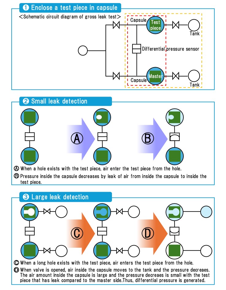
Gross leak test
Carry out gross leak testing using differential pressure type air leak testing. The leak rate of the test piece is detected as values by placing test piece and master into small capsules and comparing the pressure. For example, in the case of 1612 size, it is possible to measure up to equiv. 2×10⁻⁷Pa・m³/s equivalent standard leak rate.
Fine leak test
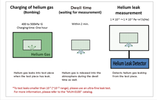
In order to test for minute defect apertures which cannot be detected using gross leak measurement, high-sensitivity type measurement called fine leak measurement is carried out using helium gas rather than air. Before measurement begins, the test piece is placed in a chamber (a pressure vessel to be charged with a helium atmosphere) and filled (bombed) with helium to at least 100 kPaG. If minute defect aperture(s) are present in the test piece, helium gas will enter the test piece through these apertures, and the helium partial pressure inside the test piece will gradually rise. After being bombed with helium for a set length of time, the test piece is removed from the chamber. Any helium gas which entered the test piece through the defect apertures will be discharged into the atmosphere immediately after removal from the chamber. Fine leak measurement detects the volume of this helium gas discharged into the atmosphere to measure the leak rate of the test piece. The amount of helium gas which enters the test piece depends on the internal volume of the test piece, the helium bombing pressure, and the helium bombing time. Furthermore, as the volume of helium gas discharged decreases over time, the detectable helium gas volume also decreases. Thus, time management after the test piece is removed is critical to the process. At FUKUDA, we call the time elapsed over this period “dwell time.”
Test piece and dwell time
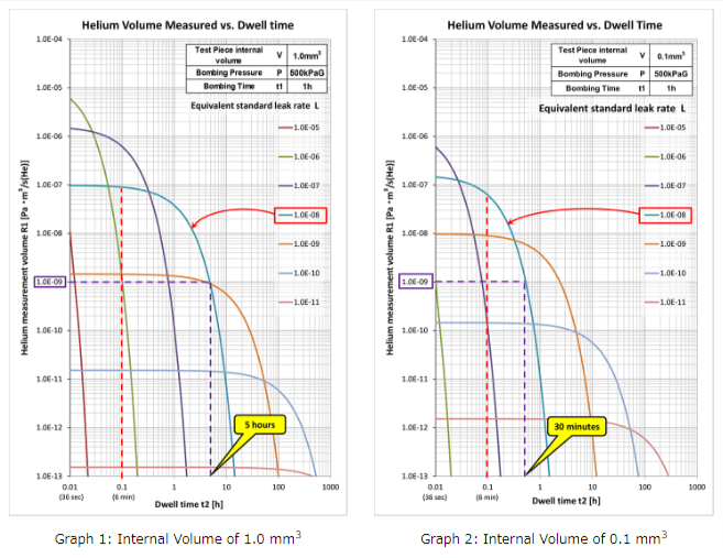
The dwell time varies depending on the internal volume of the test piece, the helium bombing pressure, and the helium bombing time.For example, consider the dwell times if the internal volumes of two test pieces are 1.0mm³ and 0.1mm³.
The equivalent standard leak rate L expresses the air leak flow rate per second from a pressure difference (100kPa) at a temperature of 25℃ when the high-pressure side is at atmospheric pressure and the low-pressure side is a vacuum. Making accurate comparisons is problematic as the air leak rate varies depending on the pressure applied and the measurement conditions (temperature). However, conditions can be standardized by conversion to the values of a set state known as the equivalent standard leak rate, enabling comparison and consideration of leak rates.
Fine leak measurement results are expressed as the helium measurement volume R1 of the elapsed time (dwell time,) and are not air leak rates. As noted above, it is necessary to make a conversion to the equivalent standard leak rate L based on this helium measurement volume result R1.
The above graphs show the relationships between equivalent standard leak rate L and helium measurement volume R1 for test piece internal volumes of 1.0mm³ (Graph 1) and 0.1mm³ (Graph 2) under the conditions of helium bombing pressure 500 kPaG and helium bombing time of one hour. A higher equivalent standard leak rate L means a greater leak rate, and therefore also an increased helium measurement volume R1. Consequently, as the time required for the helium gas to escape decreases, the time in which detection is possible also becomes shorter. In addition, a lower equivalent standard leak rate L means a smaller leak rate (i.e. smaller defect apertures), and therefore also a decreased helium measurement volume R1. Consequently, as the time required for the helium gas to escape increases, the time window in which detection is possible also becomes longer. If the test piece internal volume is decreased by a factor of 10 times, the dwell time (roughly) also decreases to 1/10 of its previous value.
Compared at an equivalent standard leak rate of L: 1.0×10⁻⁸Pa・m³/s, at the 0.1 hour (6 minutes) stage from the test piece with an internal volume of 1.0mm³ a helium measurement volume R1 of approximately 9.0×10⁻⁸Pa・m³/s (He) is detected; the test piece with an internal volume of 0.1mm³ returns approximately 6.0×10⁻⁸Pa・m³/s (He), and - as can also be seen on the graph - the helium gas discharge volume is beginning to decrease.
At a helium measurement volume R1 threshold value of 1.0×10⁻⁹Pa・m³/s (He), detection is possible from the test piece with an internal volume of 1.0mm³ within five hours, but within approximately 30 minutes for the test piece with an internal volume of 0.1mm³; after this point, helium gas has escaped and accurate measurement is no longer possible. Therefore, the dwell time to be managed varies depending on the test piece internal volume, and also leak rate to be measured vs equivalent standard leak rate. In particular, even at the same equivalent standard leak rate, as the amount of helium gas to bomb the test piece decreases due to the smaller internal volume of the test piece, the shorter dwell time is required. Therefore, pre-testing and rigorous time management are necessary for each test piece. Due to the extremely small internal volume of MEMS devices, it is necessary to select a measurement instrument with both high precision and accurate time management.