Leak Testing Components with High Temperature
Leak Testing Components with High Temperature
Powertrain-related components (engine, transmission etc.) reaches high temperatures during their manufacturing process; leak testing such components can cause many issues. Temperature offset function has been developed to eliminate issues when leak testing high-temperature components. This page discusses the principles of the temperature offset function.
Issues with Temperature Offsetting/Previous Measurement Method
Issues in the Manufacturing Process
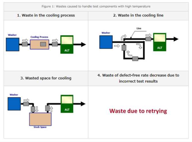
In general, it is known that leak measurement is severely compromised if the tested component has a temperature that is higher than a certain level. Methods as shown in Figure 1 have been used to avoid this issue. However, there are many 'wastes' associated with these methods such as the requirement of additional cooling process and/or cooling line and additional footprint, as well as reduction of defect-free rate due to incorrect test results.
Issues with Previous Offset Method
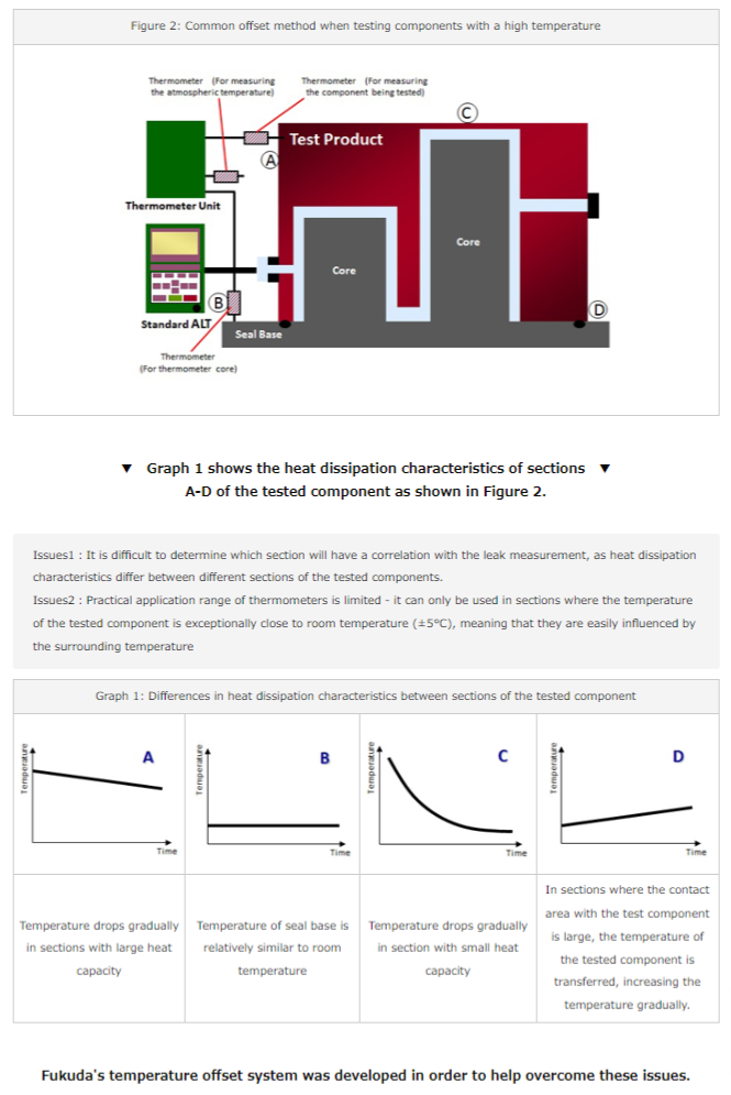
When the component subject for leak testing has a high temperature, the temperature of the said component as well as jigs and room temperature were measured to work out the correlation with leak measurements and obtain the correlation coefficient, which were applied to the leak test (see Figure 2). However, there are following issues associated with this method.
Fukuda's Temperature Offset Method
Principle of Leak Tester with Temperature Offset
Fukuda's leak tester with temperature offset considers the temperature effect as the changes in air temperature within the tested component. This means that the overall changes in temperature that incorporates not only the temperature of the tested component, but also the surrounding temperature. In addition, the data gained from differential pressure gauge is used to determine the temperature, instead of the use of thermometers. As shown in Figure 3, an enclosed structure (temperature sensing elements) is set up to collect only the temperature changes within the tested component, and the leak testing of this section is carried out with a TMD unit, with the changes in air temperature being worked out by measuring the changes in differential pressure. Leak measurement of tested components is carried out as per normal using FL-612. From these leak test values, data as shown in graphs 2 and 3 are obtained. Plotting this relationship in a scatter diagram (Graph 4) reveals a certain level of correlation, which can then be expressed as a correlation coefficient. Temperature offset can be applied by subtracting the changes in temperature from the measured value based on the above correlation.
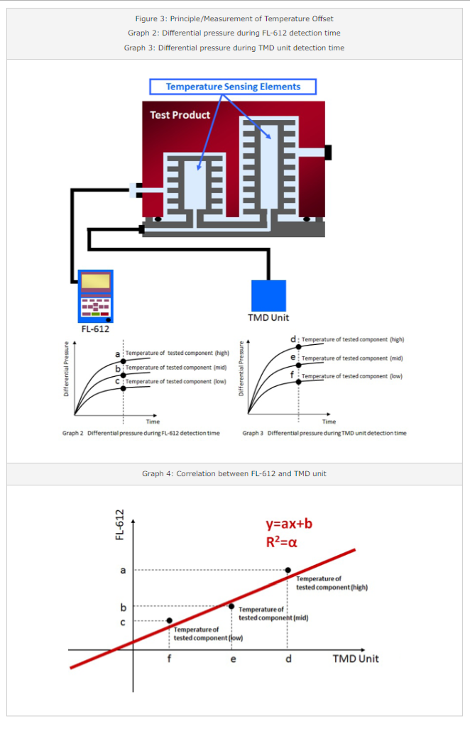
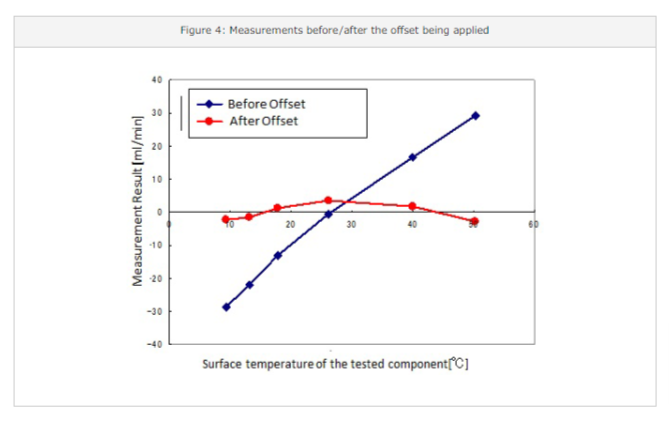
▼ A practical temperature offset can be applied by doing calculations based on ▼
the correlation coefficient gained from the method described above (Figure 4).
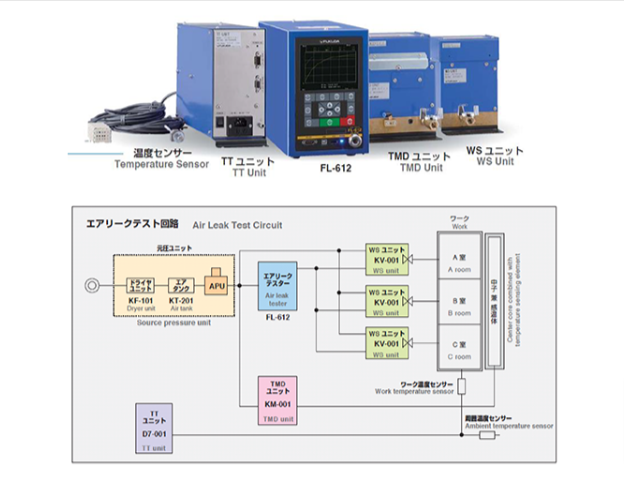
▼ The circuitry diagram of the temperature offset measurement circuit system is as follows. ▼